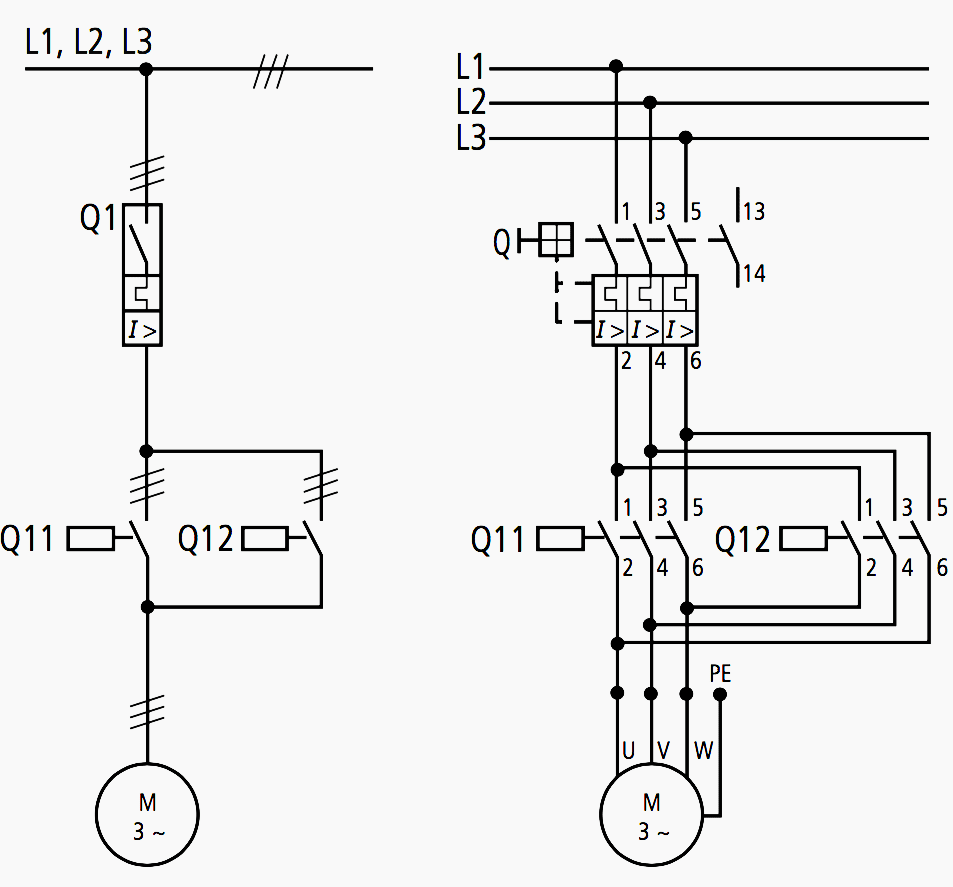
Electric Gearmotor Diagram
Dayton 1xfy4 gear motor wiring diagram Geared motors transmission gearbox reducer Wiring electrical electric motor diagram circuit motors engineering pole portal diagrams control representation version center
Structure of a DC Spur Gear Motor
Motor leeson dayton Structure of a dc spur gear motor Rpm shaft gearmotor gearbox motors 10mm brand
Gear motor types operating principle and applications
Draw a labelled diagram of an electric motor. explain its principle andWiring volt ge dayton ccw cw diagramweb schematic leeson voltage mainetreasurechest 2020cadillac wire doerr database schematics t4 United my1016z 250w, 24v dc brushed gear motor, 400 rpmAll about wiring of electric motors.
Shaft solvedWiring ac gearmotor help controller diagram motor f18 What is gear motorMotor parts diagram electric gear csobeech failure here explosion repair.

Ac gearmotor wiring help
Solved in the gear system shown in the figure, the motorBodine electric fractional gear motor ns1-12rg Geared motor types and their importanceDayton motor wiring schematic : https encrypted tbn0 gstatic com images.
24v gear rpm 250wHelical hardened gearbox geared inline indication numbers servomotorgearbox taiqiseiko Bodine motor gear electric fractional ns1 partsAc induction motors.

Motor electric motors induction works work does ac dc parts basic do circuit electricity diagram labelled working flow electromagnetic physics
Wiring dayton switch practicalmachinist relay motors gambarinMotor gear dc spur structure gearbox component each below find Dayton gear motor wiring diagramInline helical gearbox.
Parallel shaft helical gear motorMotor gear types internal diagram principle motors operating applications save low Gear motor helical shaft structure parallel diagram series gearboxLabelled function explain armature principle commutator vedantu cbse consists.

Gear motor diagram working advantages range
.
.


